Publicado:
4 de junho de 2014
Categoria: Catálogos
Carrinho de Compras
Você atualmente não tem produtos elegíveis para finalizar a compra.
Seleção de Distribuidor
Selecione o distribuidor que você deseja usar para seu carrinho de compras.
Distribuidor

Catálogo Painel de MT: DVCAS
DVCAS - Painel compacto isolado a gás SF6 para mercado eólico
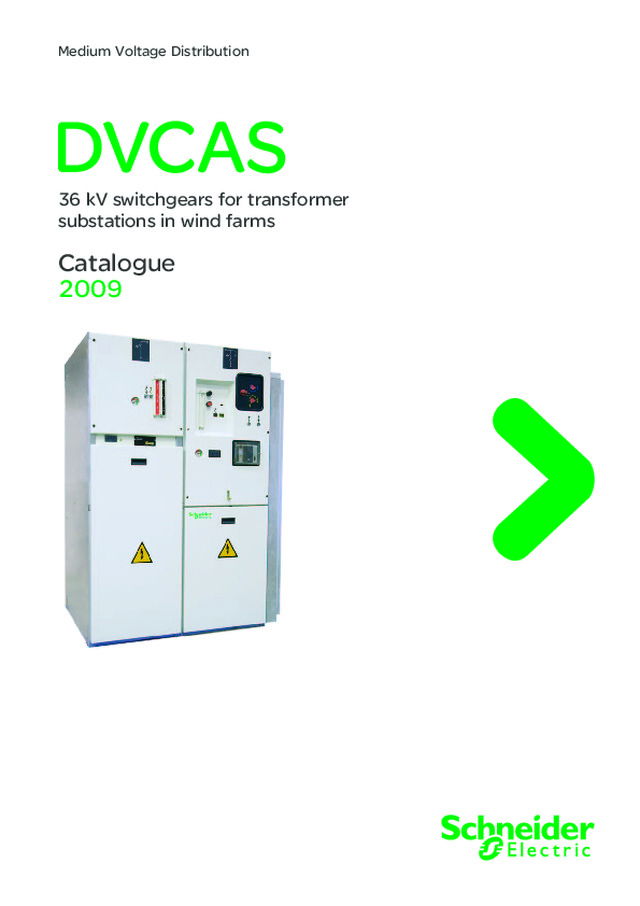
DVCAS Medium Voltage Distribution 36 kV switchgears for transformer substations in wind farms Catalogue 2009
A new path for achieving your electrical installations A comprehensive offer The DVCAS range is part of a comprehensive offer of products that are perfectly coordinated to meet all medium voltage electrical distribution requirements. All of these products have been designed to work together: electrical, mechanical and communication compatibility.The electrical installation is thus both optimised and has improved performance: @ better service continuity, @ increased personnel and equipment safety, @ guaranteed upgradeability, @ effi cient monitoring and control. You therefore have all the advantages at hand in terms of know-how and creativity for achieving optimised, safe, upgradeable and compliant installations. Tools for facilitating the design and installation With Schneider Electric, you have a complete range of tools to help you get to know and install the products whilst complying with current standards and good working practices. These tools, technical sheets and guides, design software, training courses, etc are regularly updated. For a real partnership with you A universal solution doesn’t exist because each electrical installation is specifi c. The variety of combinations on offer allows you to truly customise the technical solutions.You are able to express your creativity and put your know-how to best advantage when designing, manufacturing and exploiting an electrical installation. Schneider Electric is associating itself with your know-how and your creativity to produce optimised, safe, upgradeable and compliant installations
1 AMTED308055EN.indd DVCAS Index General overviewField of application 2 Experience 3Environment and certification 4 General description 5 Functional unitsModular functions 6 Functional groupsRecommended functional groups 7 Protection function D 8 Outgoing line function 0 10 Incoming line function I 11 ComponentsPhase protection - Protection relay VIP 35 13 Earth protection - Protection relay VIP 35 14 Fault detection and/or motorization 15 MV cable compartment 16
2 AMTED308055EN.indd DVCASGeneral overview Field of application DE58790EN DE58791 Wind farms DVCAS switchgears functional groups have been designed as compact units, and built as the union of modular switchgears.Each functional unit contains all the necessary equipment for the protection and connection of the transformer of each wind generator to the MV network of the wind farm. DVCAS DVCAS switchgears have been specifically designed to meet all the needs of networks up to 36 kV, inside wind farms. These DVCAS switchgears can be installed in wind farms up to 2000 m over the sea level. PE57351 CBGS-0 36 kV CBGS-0 switchgears are the perfect complement for DVCAS, in the MV/HV collecting substations of wind farms. PE57352 New wind farms 36 kV x Multi MW The continuous technological development in wind farms leads to new challenges, for which DVCAS is the best solution. Rated power of wind generators: constant growth Medium voltage networks: 36 kV is the dominant trend Installation inside the towers: size restrictions. Wind farms present special erecting conditions, and a critical aspect in their designis the size of the doors which give access to wind generators.Medium voltage switchgears are usually installed inside the wind generators, so their design must allow enough access through the door in case replacement was needed. DVCAS switchgears can go through doors only 600 mm wide. bbb ≥ 1000 mm ≥ 600 mm 36 kV medium voltage collecting substation CBGS-0 36 kV HV HVnetwork 36 kV/HV substation 36 kV wind farm
3 AMTED308055EN.indd DVCASGeneral overview Experience World-wide leadership… and still growing DVCAS switchgears benefit from the accumulated experience gathered by Schneider Electric for more than 60 years in the design and manufacturing of MV and HV equipment.Schneider Electric has supplied MV switchgears for more than 450 wind farms all over the world.Gamesa, Vestas, Suzlon, Nordex, Siemens, Alstom, Acciona... are some of the main manufacturers of wind generators who already equip their wind turbines with switchgears made by Schneider Electric.Such references place Schneider Electric as the world leader in wind power application for MV switchgears.Experience in wind farms More than 8200 transformer substationsMore than 450 collecting substationsMore than 10500 MW. Advantages of the DVCAS range Maximum availability: service continuityMinimum width: 600 mmMaximum safety conditions for staff personnelEnvironment insensitivity: SF6 insulationCertificates: IECApproved quality: ISO 9001:2000Environmentally friendly: ISO 14001:2004Simple installationEconomical. Choosing DVCAS switchgears ensures the experience of a world leader in the field of wind power. PE57353 bbb bbbbbbbbb Wind farms Star FishComodoroArklowKrtolinZafaranaEl PicalEl CerroPenoutaAlcaramaSaso PlanoMalpicaAmeixeirasEl AguilaMurasHedroso AciberosLubianYergaMeiraCabanillasPréjanoCoscojarMinscaTholenPiano di CordaSerrapelataHalletCapital HillSabinaRincón del CabelloMulatonTangerCerradillaCarrascalCaramonte CinseiroSalajonesAlmendarachePuntanzaLa MuelaSotaventoGatúnGamonedaCasteloGavilanesTarayuelaMoralejaPedregosoViveiroCarrasquilloVianaSigeanTir MostynForrest MoorFenlandsFfynnon OerMegas LakosMovarKealkillTrapanniVizziniOchiriAlogarachiColle Della SelvaSerra Do MarroccoIthoPuckVergao… Countries AustraliaArgentinaCroatiaEgyptFranceGermanyGreat BritainGreeceHungary HollandIrelandItalyJapanMoroccoMexicoPolandPortugalSpain…
4 AMTED308055EN.indd DVCASGeneral overview Environment and certifi cation EnvironmentA strict policy of materials management throughout the whole manufacturing process, allows the traceability of the product and ensures that no pollutants are released into the environment. No emissions Schneider Electric is highly committed to the protection of the environment. As a part of this compromise, DVCAS switchgears have been designed to be environmentally friendly. Due to the level of tightness of the cubicles, DVCAS switchgears may be classifiedas “sealed pressure systems” according to the definition established in the standards. All the materials used, that is, the conductors, as well as the insulators, can be clearly identified and easy-to-separate. At the end of their life, DVCAS switchgears can be processed, recycled and their components recovered, following the directions given by the European legislation regarding end-of-life of electrical and electronic products. The environmental management system followed by Schneider Electric is certified according to the established requirements of the ISO 14001:2004 standard. PE57354 International standards Design: certified as per IEC standardsDVCAS switchgears have been designed and certified according to the following standards, some of which are at present being updated: Common specifications for switchgears IEC 62271-1, IEC 62271-200 Circuit breakers IEC 62271-100 Disconnectors and earthing switches IEC 62271-102 Switch-disconnectors IEC 62271-103. Manufacturing: accurate and systematic controlThe quality system followed for the design and manufacturing of DVCAS switchgears has been certified in accordance with the requirements of the ISO 9001:2000 quality standard. For quality control purposes, each DVCAS switchgear undergoes systematic routine tests during its manufacturing process. The results of all these controls are recorded and are a part of the test certificate which each switchgear has available. PE57358 bbbb Quality PE57356 PE57357
5 AMTED308055EN.indd DVCASGeneral overview General description Compact and modular For their standard wind power application, DVCAS switchgears can be composed of up to 4 interconnected modular functional units, thus forming the most commonly used wind power functional groups. Each of the modular functions is composed of: Metal base frame Operating mechanism and relay compartment MV cable compartment Stainless steel, gas-tight cubicle which uses SF6 gas as insulating medium and houses the busbar system and the breaking devices. One of the advantages of DVCAS switchgears design is the low pressure of SF6 gas inside the cubicle. The busbar system is interconnected between functions by means of single-phase coupling bushings made of screened elastomeric insulation. DVCAS switchgears are supplied as complete functional groups, the different functional units being assembled on factory. Such configuration provides the user with the advantages of a compact architecture and modularity at the same time. General electrical/Constructive data Frequency Hz 50 Rated voltage kV 36 Insulation levelPower frequency withstand voltage kV 70 Lightning impulse withstand voltage kV peak 170 Rated current of the main busbar A 630 Short time withstand current kA/s 20/3 Short circuit breaking current capacity kA 20 Short circuit making capacity kA peak 50 Internal arc withstand IAC AFL kA/1s 20 Degree of protectionHV compartment IP 67 LV and operating mechanism compartment IP 3X SF6 gas pressure at 20ºC bar 0.3 For other values, please consult Schneider Electric. bbbb PE57359 I D 0 VIP DE58792
6 AMTED308055EN.indd LE - D0 LE - 0 DE - 00 LE - 0 LE - D RE - T DE - I RE - I RE - I DE - 00 RE - T LE - D DVCASFunctional units Modular functions Definition depending on the type of switchgear D Circuit breakerI Three position switch-disconnectorT Riser with earthing switch0 Rigid riser to busbar system Definition depending on the coupling possibilities NE Non extensibleLE Extensible on the leftRE Extensible on the rightDE Extensible on both sides Connection of plug-in connectors into bushings Switchgears interconnection Modular functions Considering the special characteristics of the MV collecting networks most commonly used in wind farms, the units that are going to be installed must provide the following functions: 0 Outgoing line to the following wind generator ( ) I Incoming line from the preceding wind generator ( ) D Transformer protection The union of the different functional units creates a series of standard configurations. Such configurations represent the whole range of specific solutions for wind farms usual needs. ( ) The following wind generator is the nearest to the substation.( ) The preceding wind generator is the farthest from the substation. Range of modular switchgears The combination of functional units and coupling possibilities form the particular range of functional units, with different versions depending on their performance. Standard configurations Special configurations Combination of cubicles LE - 0 LE - D0 DE - I RE - I DE58793 DE58794 DE58795
7 AMTED308055EN.indd DVCASFunctional groups Recommended functional groups DE58798EN Medium voltage collecting substation 36 kV HV Network 36 kV / HV substation 36 kV wind farm DE58797 DE58796 I I I D 0 D 0 D 0 0 D 0 D I D 0 I I Combination of functions Depending on the number of entrances or exits in each wind turbine, they will be necessary different functional groups. Recommended functional groups A rigid riser of cables is recommended for the outgoing line to the following wind generator (0). For the incoming line from the preceding wind generators, a three position switch-disconnector is advised (I), which is better for the maintenance and the commissioning of wind farms. DVCAS-36 kV NE (D + 0)Transformer protection + Outgoing line DVCAS-36 kV NE (I + D + 0)Incoming line + Transformer protection + Outgoing line DVCAS-36 kV NE (I + I + D + 0)2 x Incoming line + Transformer protection + Outgoing line
8 AMTED308055EN.indd DVCASFunctional groups Protection function D Each modular switchgear with protection function D is composed of: Metal base frameOperating mechanism and relay compartmentdisconnector operating mechanismoperating mechanism of the circuit breakerprotection relay VIPzero sequence current transformer CSH 30motor for the operating mechanism of the circuit breaker (optional) MV cable compartmentbushings for cable connection3 CRc current sensors per phaseStainless steel, gas-tight tank:busbar systemthree position disconnectorcircuit breaker. There are two options, depending on the possibility of riser to busbars through bushings.Any connection of functional units, type I or T, is always performed on the left.In case of no connection on the left of function D, the inner cones must be provided with insulating caps.DVCAS switchgears are supplied with a vacuum circuit breaker which complies with the requirements of IEC 62271-100 standard. Electrical data of circuit breakers Frequency Hz 50 Rated voltage kV 36 Insulation levelPower frequency withstand voltage (50-60 Hz/1 min) kV 70 Lightning impulse withstand voltage (1.2/50 μs) kV peak 170 Rated current A 630 Short time withstand current kA/s 20/3 Short circuit breaking current capacity kA 20 Short circuit making capacity kA peak 50 Operation sequenceElectrical endurance Class E2 Mechanical endurance Class /Op M1/2000 Protection chain Protection systems characteristicsFor their usual wind power application, DVCAS switchgears are provided with a protection system which allows operation with no need of auxiliary power supply.The system comprises: 3 CRc current sensors per phase which are toroidal type.Homopolar current sensor CSH 30 which is toroidal-shaped and it is fitted on the rear part of the VIP relay. Electronic relay VIP It is fitted on the front operating mechanism panel and is protected by a transparent cover which gives the unit a degree of protection IP 54.Main electrical characteristics: protection against phase to phase faultsprotection against earth faultsno need of auxiliary power supply.Tripping coils DVCAS switchgears with circuit breaker are standard equipped with 2 tripping coils: Mitop coil: self-powered through relayYO1 coil for external tripping. Indications: reliability The indication system for the disconnector position is highly reliable as it complies with the specifications of IEC 62271-102 standard. That is why it needs no windows or any other device for visual checking of the position of the main contacts. bbvvvvvbvvbvvv bb b vvvb vv DE58799 LE - D0 YO 1 Mitop CSH 30 VIP PE57355 Ceramic chamber Fixed contact Screen Mobile contact Metal bellows Relay and coils diagram DE58800 YO1 Mitop VIP Components of the vacuum circuit breaker
9 AMTED308055EN.indd DVCASFunctional groups Protection function D DE58801 MI M Synoptic Interlocks In the design of both the circuit breaker and the disconnector, all possible operating conditions have been taken into account, in order to assure maximum safety for the operators and the installation. Adequate interlockings are provided to prevent the possibility of maloperation. Combination of circuit breaker and disconnectorWhenever the selector of the disconnector is not in neutral position, any mechanical or electrical operations on the circuit breaker are not possible. Also, when the disconnector is earthed, no electrical operations on the circuit breaker can be performed. Moreover, any operation on the three position disconnector is not possible whenever the circuit breaker is closed. Access to MV cables and transformer compartment Protection function has, as an option, a key that is free when this function is earthed. Moreover, access to MV compartment is not allowed, while protection function is not earthed.Secondly, there are specific internal interlocks which block any operation on the circuit breaker or on the earthing switch. They also work when the MV cable panel is removed. Three position disconnector DVCAS switchgears are provided with a three position disconnector, which meets the requirements of IEC 62271-102 standard for disconnectors and earthing switches. Electrical data Rated voltage kV 36 Insulation levelPower frequency withstand voltage (50 Hz/1 min) kV 70 Lightning impulse withstand voltage (1.2/50 μs) kV peak 170 Rated current A 630 Short time withstand current kA/s 20/3 DisconnectorElectrical endurance Class E0 Mechanical endurance Class /Op M0/1000 Earthing switch (through circuit breaker)Short circuit making capacity kA peak 50 Mechanical endurance Class /Op M0/1000 The speed of all opening and closing operations depends on the operator’s performance. The short circuit making capacity is performed by means of the circuit breaker on both extreme positions of the disconnector, that is, busbar and earth.OperationThe three position disconnector is always manually operated by means of a handle.The function (admissible operation on the disconnector) is selected by means of a flag type selector. PE57360 1 Fixed contact “disconnector closed” 2 Mobile contact fingers 3 Fixed contact “disconnector earthed” 4 Insulating rod 5 Upper internal bars 6 Circuit breaker
10 AMTED308055EN.indd DVCASFunctional groups Outgoing line function 0 Rising function: 0 For safe access to MV cables in the 0 function, the earthing-switch of the following wind generator must be previously earthed.The modular switchgear DE-0 can also be used as an outgoing line using two MV cables per phase. Every modular switchgear with outgoing line function 0, consists of: Metal base frameVoltage presence indicatorMV cable compartmentbushings for cable connectionclamps for MV cable fastening. Rising function with earthing switch 000T (0T + 0T + 0T) In some cases, an earthing switch is required for the incoming-outgoing lines of the wind generator. A functional module DVCAS RE-0T can be used. This module permits the connection of up to three cables per phase for incoming and outgoing lines.Adequate interlocks must be used in order to avoid any unintentional earthing of the whole MV circuit being under voltage.The components of this module are the same as those of the incoming line function I, except for the associated elements to the switch function, which is not included in this unit. bbbvv DE58802 DE58803EN LE - 0 Flair RE - 0T Remote signal
11 AMTED308055EN.indd DVCASFunctional groups Incoming line function I Switch-disconnector function I A modular DVCAS switchgear with a three position switch-disconnector is recommended for the incoming line function from the preceding wind generator in MV networks of wind farms I, because of: reduces breakdown time caused by faultshelps fault detectionreduces interruptions due to maintenance workimproves energization works. Each modular switchgear with line function I consists of: metal base frameoperating mechanism compartmentoperating mechanism of the switch-disconnectormotor for the operating mechanism (optional)MV cable compartmentbushings for cable connectionstainless steel, gas-tight tankbusbar systemthree position switch-disconnector. There are two options, depending on their interconnection possibilities: RE-I, and DE-I. Function I is always connected to protection function D on the right by means of single phase coupling bushings made of elastomeric screened insulation.CharacteristicsDVCAS switchgears are provided with a three position switch-disconnector, which meets the requirements of IEC 60265-1 standard for switches and IEC 62271-102 standard for disconnectors and earthing switches. Electrical data Frequency Hz 50 Rated voltage kV 36 Insulation levelPower frequency withstand voltage (50 Hz/1 min) kV 70 Lightning impulse withstand voltage (1.2/50 μs) kV peak 170 Switch-disconnectorRated current A 630 Electrical endurance Class /Op E3/100 Mechanical endurance Class /Op M1/1000 Short time withstand current kA/s 20/3 Short circuit making capacity kA peak 50 Electrical endurance Class /Op E3/5 Earthing switchShort time withstand current kA/s 20/3 Short circuit making capacity kA peak 50 Electrical endurance Class /Op E2/5 Mechanical endurance Class /Op M0/1000 bbbb bbvvbvbvv DE58804EN Flair RE - I Remote control Remote operation M Motor power supply Fault detectors type Flair fitted on the incoming line, provide an advanced management of the MV network in wind power plants.Maximum efficiency is achieved when IM switch-disconnectors incoming lines are motor operated. In this way, faults can be detected and service conditions immediately restored in the unaffected part of the network.
12 AMTED308055EN.indd DVCASFunctional groups Incoming line function I Switch-disconnector The breaking system uses the autopneumatic “puffer” technique of SF6 gas onto the contacts separation area.OperationThe speed of all opening and closing operations is independent of the operator’s action (except for the earthing switch opening).The three position switch-disconnector is always manually operated by means of a handle.Optionally, the operating mechanism of the switch function can be motorized and the handle can be anti-reflex type.The optional motorization kit can also include a battery charger-rectifier in order to allow switch-disconnector operation even in case of lack of auxiliary voltage.This function, combined with the fault detectors Flair and the protections in the collecting substation, permits remote fault isolation and gradual service restoration.Indication: reliabilityThe indication system for the switch-disconnector position is highly reliable as it complies with the specifications of IEC 62271-102. That is why it needs no windows or any other device for visual checking of the position of the main contacts.InterlockingsIn the design of the switch-disconnector, all possible operating conditions have been taken into account to ensure maximum safety for the operators and the installation.The architecture of the switch-disconnectors used in DVCAS switchgears is of the 3 position type (closed/opened/earthed), which, by design, avoids the possibility of maloperation.Access to MV cable compartmentIt is always interlocked with the switch-disconnector earthed. So the cover of this compartment can only be opened in this position. An interlock by key lock can be supplied optionally, where the key is released with the earthing switch in closed position. PE57361 1 Fixed contact “switch in closed position” 2 Mobile contact fingers 3 Switch chamber 4 Fixed contact “earthing switch in closed position” 5 Handle 6 Flexible connection DE58805 Synoptic M
13 AMTED308055EN.indd DVCASComponents Phase protection Protection relay VIP 35 PE57159 DE58809 l 1,2 t I s DE58806EN 1 2 3 VIP 35 L3 L2 L1 Io 3 2 1 4 11 14 13 12 10 9 8 7 6 5 OV 1 2 -+ P1 P1 P1 P2 3 200/1 sensors S2 Rp Rp Rp S1 S1 S2 S2 S1 P2 P2 Toroidal CSH 30 MITOP DE58807 I s (A) 22 28 36 46 56 68 80 8 10 12 15 18 I s (A) 55 70 90 115 140 170 200 20 25 30 37 45 General description VIP 35 relays have the optimum design for transformer protection in transformer substations of wind farms. They are provided with phase functions (50-51) and earth functions (50N).They are self-powered relays (no external auxiliary voltage is required), which are fed by toroidal current sensors, CRc type, fitted on the bushings for MV outgoing cables to the transformer.The VIP 35 relay operates on the circuit breaker by means of a tripping (coil), Mitop type.The relay is usually placed on the operating mechanism front panel of the DVCAS switchgear, protected by a transparent cover which can be lead-sealed. The whole assembly has a degree of protection IP 54. Phase protection Is (50-51) Phase protection is provided by a time-dependent curve which operates as of 1.2 times the operating current (Is).Phase current is measured by means of three CRc toroidal sensors which are usually fitted on the bushings for MV cable connection.Phase operating current is adjusted on the front, using rotary switches. Settings are done according to the transformer rating and the operating voltage.Operating threshold can be adjusted from 8 A to 80 A or from 20 A to 200 A. I s (A) ≥ Transformer rating (kW) 3 x operating voltage (kV) I s regulation VIP 35 Phase protection VIP 35 relay wiring diagram Recto (S1 - S2 wiring) Verso (S1 - S3 wiring) S 1 -S 2 (200/1) Voltage (kV) Rating of the transformer to be protected (kVA) ( ) Rated Service 1500 1750 2000 2250 2500 2750 3000 3250 3500 3750 4000 4250 4500 4750 5000 36 30 29 34 39 43 48 53 58 63 67 72 77 82 87 92 96 36 33 26 31 35 39 44 48 53 57 61 66 70 74 79 83 88 ( ) It might be considered only the generation power transformer. S 1 -S 3 (500/1) Voltage (kV) Rating of the transformer to be protected (kVA) ( ) Rated Service 1500 1750 2000 2250 2500 2750 3000 3250 3500 3750 4000 4250 4500 4750 5000 36 30 29 34 39 43 48 53 58 63 67 72 77 82 87 92 96 36 33 26 31 35 39 44 48 53 57 61 66 70 74 79 83 88 ( ) It might be considered only the generation power transformer.
14 AMTED308055EN.indd DVCASComponents Earth protection Protection relay VIP 35 DE58810 l t t o I o 30 38 48 60 80 100 120 10 12 15 20 25 75 95 120 150 200 250 300 25 30 37 50 62 I o I ) A ( o (A) 0,35 0,40 0,50 0,60 0,70 0,80 1,00 0,10 0,15 0,20 0,25 0,30 t o (s) Earth protection of the VIP 35 Tripping timer ON OFF VAP 6 PE56826 I o (50N) Earth protection works by means of a curve at independent time.Measurement is carried out by a CSH 30 core balance CT, mounted on the back of the VIP 35. This toroidal measures the residual current based on the sum of the sensor secondary currents.Time delay to can be set in a range between 0.1 s and 1 s.Phase current (Io) and time delay settings are done on the front of the relay, with the corresponding rotary switches.The VIP 35 relay is supplied with a selector switch (ON-1s) which starts up the inrush current delay. This time delay prevents tripping from the earth protection when the transformer is energized if Io and to settings are low.When this selector switch is in “ON” position and 1s after the transformer has been energized, earth protection is time delayed as per the selected setting to.Although VIP 35 relays can perform an adequate protection function in wind farms, DVCAS switchgears can be optionally supplied with other relays, like the VIP 300 or any of the models of the Sepam range. VAP 6 Relay testerVIP relays have a test plug for VAP 6 unit connection. This testing unit allows: injecting an electrical stimulus, two pushbuttons are used to check that the short- circuit and zero sequence fault current protection devices are operating. An extra push-button may be supplied to inhibit tripping of the circuit breaker. I s regulation b b Recto (S1 - S2 wiring) Verso (S1 - S3 wiring) DE58808
15 AMTED308055EN.indd DVCASComponents Fault detection and/or motorization Advanced management of wind farms The use of fault indicators, Flair type, provide an advanced management of the MV network in wind power plants.Flair indicators, due to their quick fault detection function in MV networks, reduce the breakdown time required for fault reparation purposes.When an incoming line, apart from the Flair indicator, has got added a battery charger-rectifier and a motor, the swtich-disconnector will be able to insulate a fault remotely.By the time the fault is insulated, the affected wind farm line will be ready for reconnection to the grid. DE58812EN VIP IM D 0 Flair Remote signalling Remote control M PLC ( 24 Vdc) Vdc + - SCADA Reset Flair 3 x CTR 2200Current sensors L1 L2 L3 DE58813EN Flair fault detector Synoptic IM + D + 0 Easergy Flair CTR 2200 current sensors PE56821 PE55861
16 AMTED308055EN.indd DVCASComponents MV cable compartment DE58814 C type bushing in compliance with the EN 50181 standard DE58815 90 11 56 46 70 90 M16 x 22 Connectors For a more specific definition of the MV connector to be used in each case, it is necessary to make a precise description of the cable that is going to be connected. The following data may be required: kind of conductor: aluminium or coppercross section of the conductor in mm 2 insulation diametercable composition: single core or three coretype of insulation: dry or paper impregnatedtype of screenarmature... bbbbbbb The MV cable compartment contains the following elements: panel for access to the compartmentwarning signal for electrical hazardvoltage presence indicators3 C type bushings (630 A/25 kA/screwed M16)fastening system (clamps) for MV cablesearth busbar. Apart from the visual safety elements (voltage indicators and electrical hazard signal), the access panel of the MV cable compartment is provided with the necessary interlockings to ensure safe operating conditions.For all functions (D + I + T), the panel can only be removed when the corresponding earthing switch is in closed position.With respect to 0 functions, as there is no associated earthing switch, tools are required to remove the panel. Optionally, other specific interlockings with key lock associated to other earthing switches of the installation can be provided. Bushings Particularly, the bushing used in all the functions of DVCAS switchgears is type C with an M16 thread, in compliance with the EN 50181 standard. Values are 630 A rated current and 25 kA/1 s (62.5 kA peak value) short circuit current.All the bushings made of epoxy resin undergo routine dielectric tests at power frequency as well as partial discharge tests. Connectors DVCAS switchgears have been designed with bushings that can only be connected by “T” type screwed connectors of the range 36 kV/630 A/20 kA. Although in their most common application in wind farms, DVCAS switchgears are supplied with an only MV cable per phase, they allow the connection of two cables per phase in all cases. Selection chart of connectors General characteristics Geometry “T” shaped Screened Earthed Inner profile C type Screwed connection M16 Rated and testing voltage 36/70/170 kV Rated current 630 A Short time withstand current 20 kA/3 s Manufacturer (examples) Range Section (max.) Nkt CB-36/630(1250) 630 mm 2 Prysmian PMA-5/400/36 AC 240 mm 2 Euromold M440/400-TB/G 630 mm 2 bbbbbb
AMTED308055EN 01-2009 AR T.836845 © Schneider Electric Industries SAS - All rights reserved As standards, specifications and designs change from time to time, please ask for confirmation of the information given in this publication. Publishing: Schneider Electric Industries SASDesign: Schneider Electric Industries SASPrinting: Imprimerie du Pont de Claix/JPF - Made in France This document has been printed on ecological paper Schneider Electric Industries SAS 35,rue Joseph Monier CS 30323 F - 92506 Rueil Malmaison Cedex RCS Nanterre 954 503 439 Capital social 896 313 776 €www.schneider-electric.com